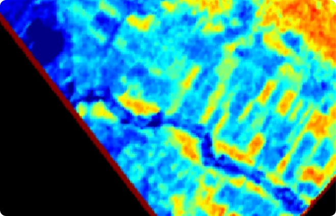
Typhoon Lekima in 2019: Image taken by the "DLAS" of Tokyo Institute of Technology (currently known as Institute of Science Tokyo)
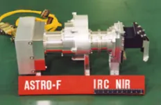
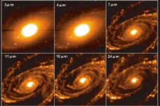
ASTRO-F/AKARI

Hodoyoshi-1

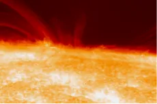
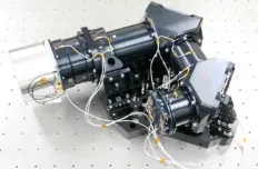
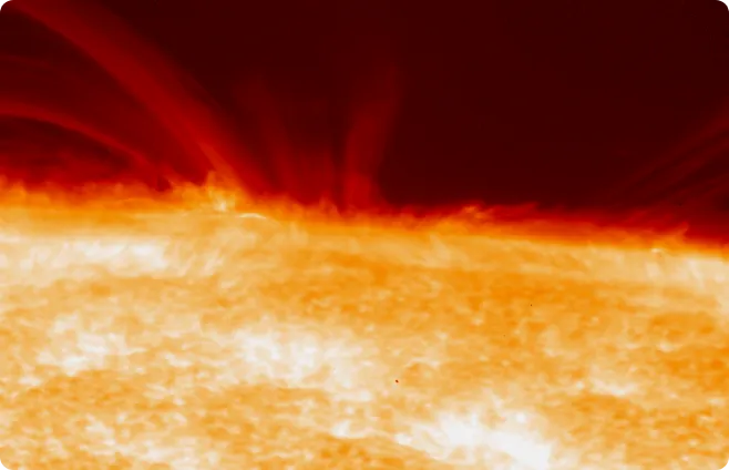
SOLAR-B/HINODE
RISING-2
CIBER-1
HAYABUSA-2 NIRS3
ISS-IMAP
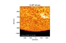
CLASP
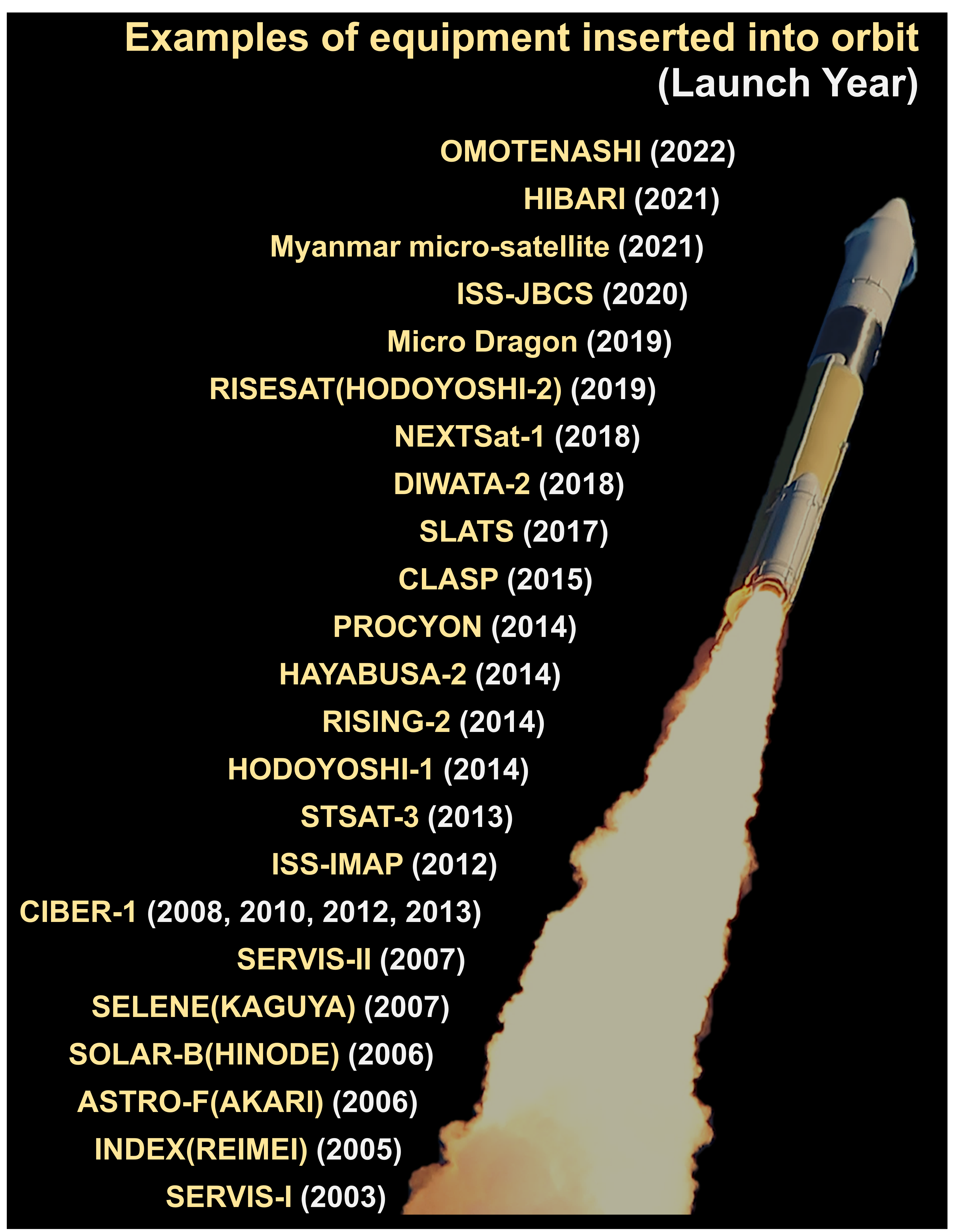
We have developed over 50 spaceborne optical instruments for a wide range of wavelengths, from deep ultraviolet to visible and thermal infrared. They are used in mission such as Earth observation, Solar observation, deep space exploration, and more. The star trackers we also developed have flight experience. The technologies accumulated through these developments are also being adapted for the mass production of commercial optical products used on the ground.
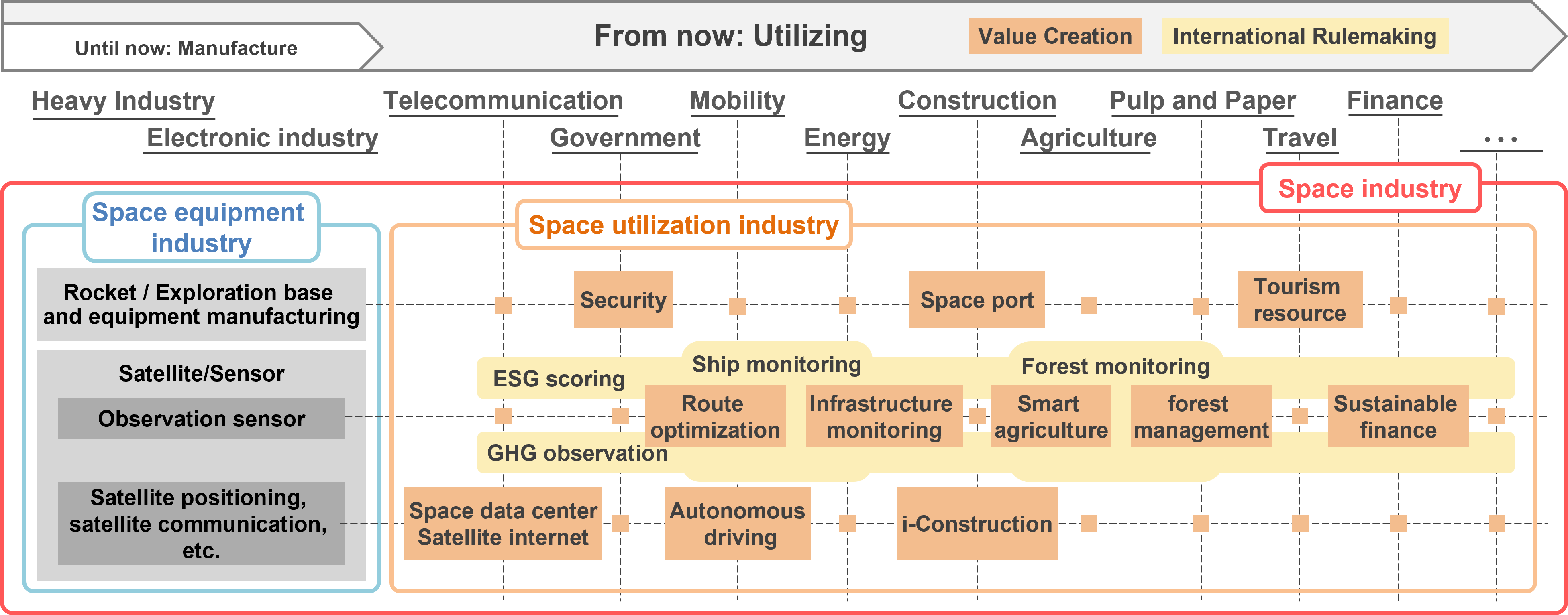
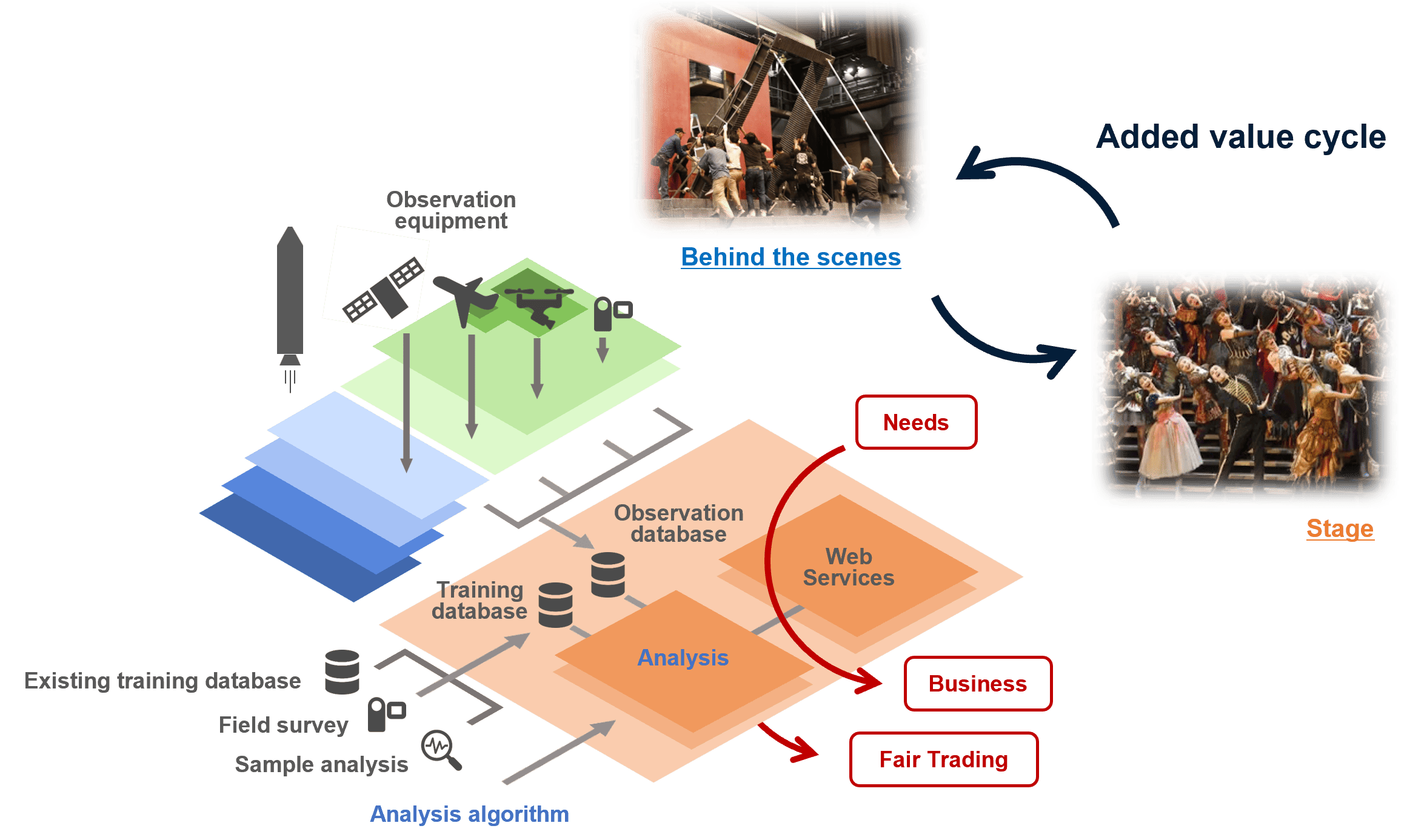
According to the traditional concept, the space industry refers to the "space equipment industry”. Today, however, a shift in thinking is required to utilize the space equipment industry as a means to support the peaceful lives of people living on the ground and to promote business development. It is important to consider the “space utilization industry” from this point of view. Taking the social added value generated by the space equipment industry on the horizontal axis and the original added value of each industrial sector on the vertical axis, a new industry will surely emerge at their intersection. We recognize the “space industry”, consisting of the space equipment industry and the space utilization industry as the value of space, and we are trying to provide a concrete template that can create and develop this value.
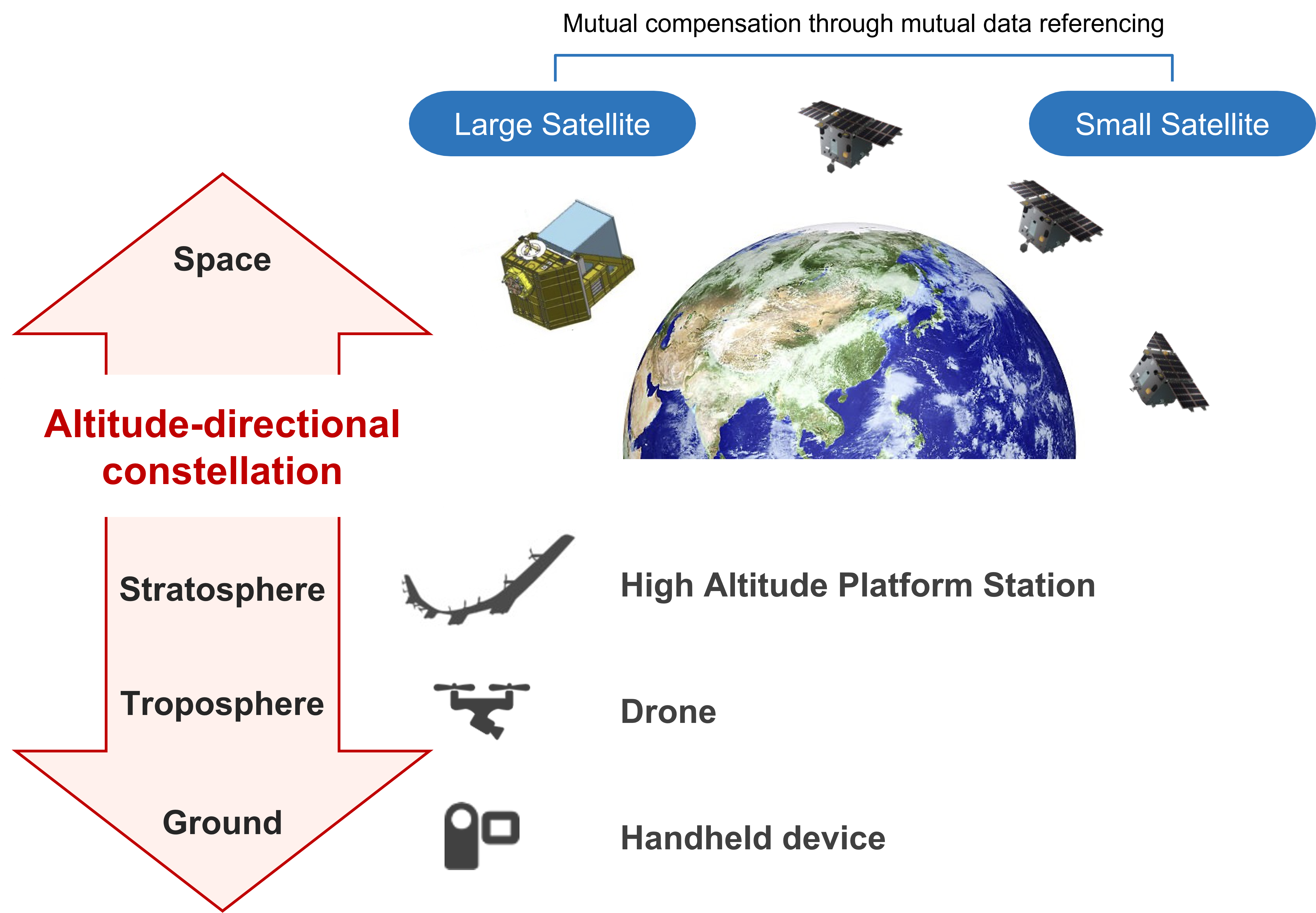
In order to enhance the “space industry”, it is necessary to promote the integration of two perspectives: a micro perspective that focuses on human activities on Earth's surface, where value is created and consumed, and a macro perspective that considers the entire planet. To achieve this, it is necessary to build not only a constellation of satellites in space orbit, but also an "altitude-directional constellation" of coupled platforms in orbit altitude direction. It is necessary to build a system of economic value circulation that can respond to market demands generated by “human activities” while socially implementing scientific ideas that utilize world-leading new technologies.
| Platforms | Features |
|---|---|
| (Small) satellites |
Suitable for wide-area observations High ground speed |
| HAPS |
Fixed-point observation High spatial resolution High temporal resolution |
| Drones |
More precise spatial resolution Shorter measurement time Lower cost |
These combinations will support new areas of business creation and security needs.
The space equipment industry is “behind the scenes” to ensure “the safety of people living and the economic circulation,” but in reality, economic value is generated and consumed not in space orbit itself, but on the ground as a “stage”. However, the space industry has room for improvement in value circulation and value sharing.The organization that is the starting point of the business is weak in terms of capital power, and if the fair distribution and circulation of profits is interrupted, it will be damaged from the bottom up, and its ability to develop markets will be easily lost. Our goal is to create a sustainable society that is healthy and has growth potential from end to end.
There is a growing trend toward achieving all “five resolutions” for visible and near-infrared telescopes installed on nano-satellites for Earth observation.
In order to increase these resolutions, there are growing efforts to realize space optics that are more compact and lightweight than conventional optics, with large image memory, low power consumption, and the ability to perform on-orbit edge computing (including AI).
However, it is difficult in general terms to satisfy the above five resolutions simultaneously.
For this reason, a so-called constellation is being considered in which each of several satellite buses is implemented
with its own unique features, and they are coordinated in orbit.
GENESIA is particularly focused on realizing imaging systems that focus on spatial, wavelength, and contrast resolution (time resolution, in principle, depends on the number of satellites placed in space orbit).
Optics envelope: 1U size
Wavelength: 0.48 - 0.62μm (visible panchromatic)
GSD: 6.5m, swath: 21km (orbital altitude 500km)
Optics envelope: 2U size
Wavelength: 0.9 - 1.7 μm (infrared panchromatic)
GSD: 15.4 m, swath: 10 km (orbital altitude 500 km)
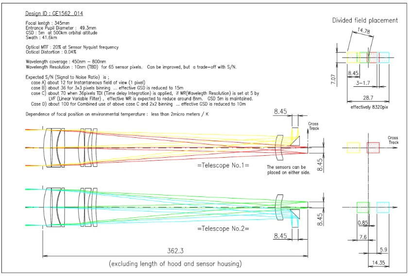
Optics envelope: 3U size
Wavelength: 0.45 - 0.80 μm (visible/infrared panchromatic)
GSD: 3 - 5 m, swath: 5 - 8.5 km (orbital altitude 500 km)
(GSD and swath can be optimized for different applications)
Optics envelope: 4U size
Wavelength: 0.45 - 1.0μm
(Wavelength selectable on orbit with LCTF:Liquid Crystal Tunable Filter)
GSD: 3 - 5m, swath: 5 - 8.5km (orbital altitude 500 km)
(GSD and swath can be optimized for different applications)
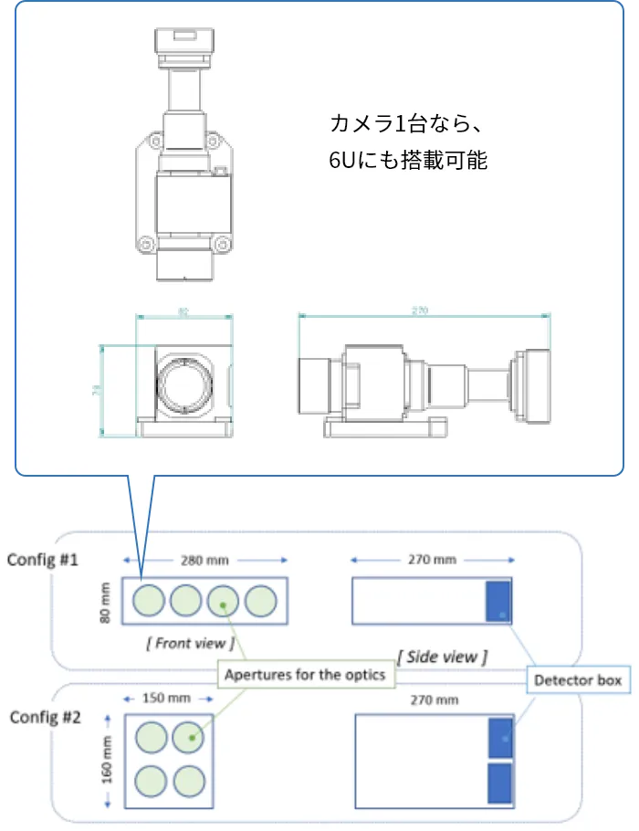
Optics envelope: 4U size
Wavelength: 4 bands from 0.45 - 1.0μm
GSD: 3 - 5m, swath: 5 - 8.5km (orbital altitude 500 km)
(GSD and swath can be optimized for different applications)
Optics envelope: 4U size
Optics envelope: 4U size
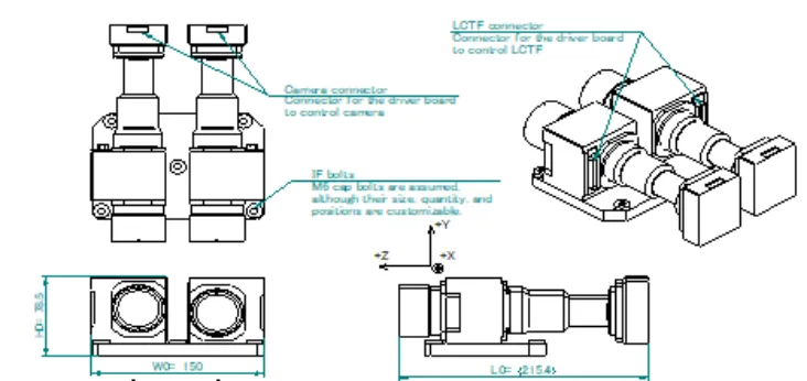
Optics envelope: 4U size
Wavelength: 0.40 - 1.6μm
(Wavelength selectable on orbit with LCTF:Liquid Crystal Tunable Filter)
GSD: 59m, swath: 97km (orbital altitude 500 km)
Optics envelope: 9U size
Wavelength: 0.40 - 1.6μm
(Wavelength selectable on orbit with LCTF:Liquid Crystal Tunable Filter)
GSD: 30m, swath: 185km (orbital altitude 500 km)

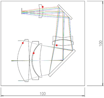
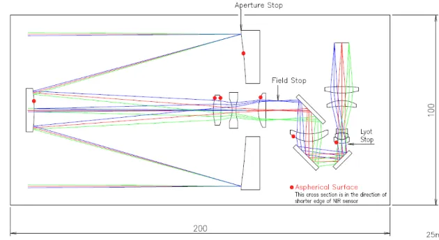
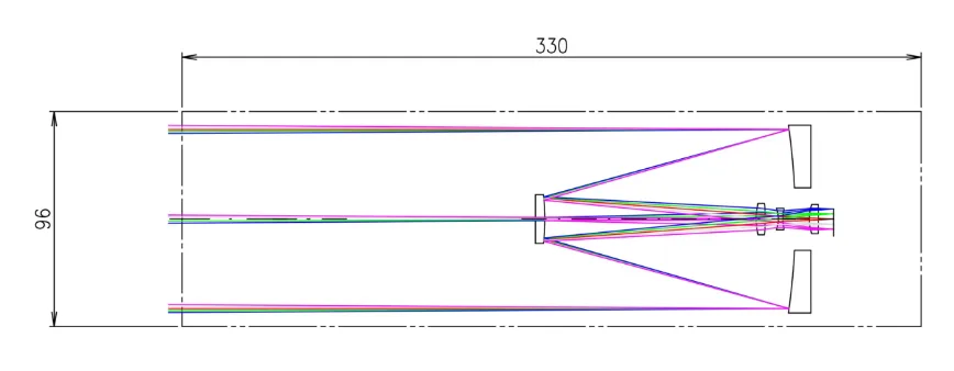
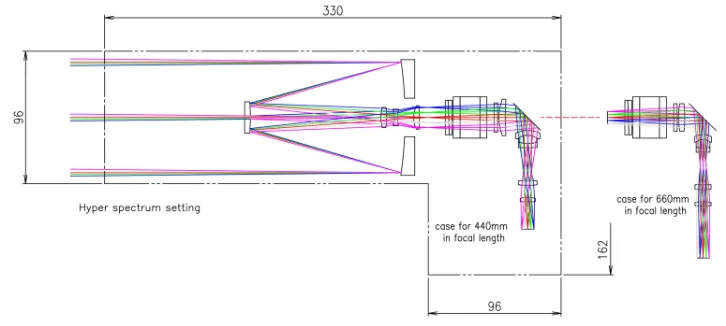
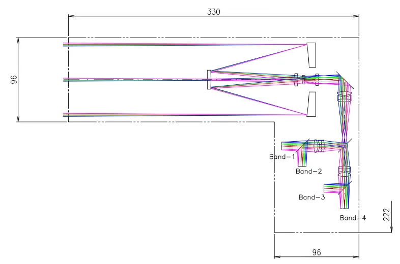
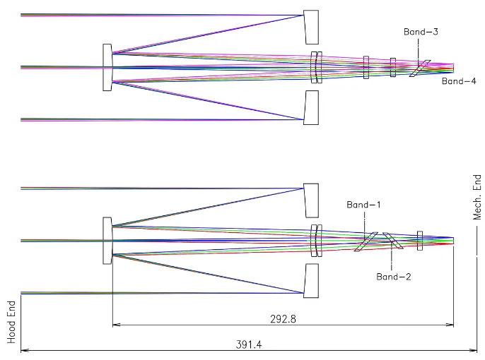
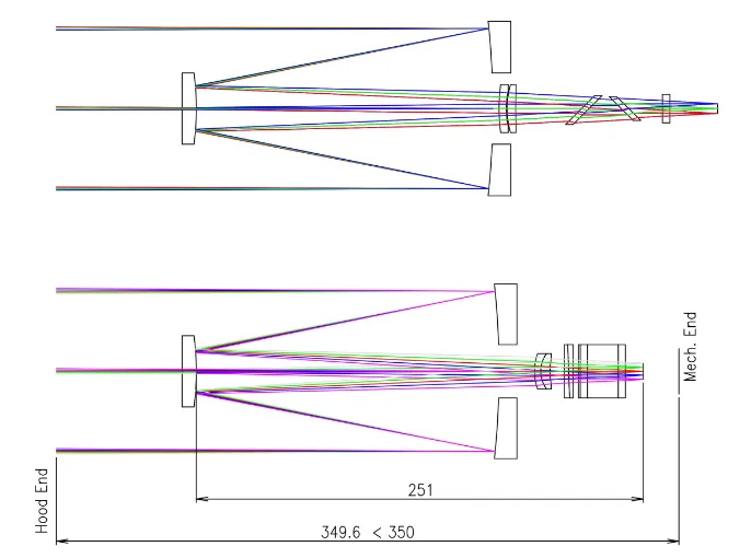
This is an example of an optical design for infrared multi-wavelength imaging in the 1.25-2.5 μm wavelength band.
Wavelength-tunable filters such as LCTF:Liquid Crystal Tunable Filter can also be used.
This optical system is designed to be installed on drones.
This design aims to create a “constellation in the orbital altitude direction” in combination with satellites.
The full angle is 80°. The distortion aberration amount is equivalent to a maximum of 1.5 pixels in an infrared detector with a pixel pitch of 15 μm (VGA). Expressed as a percentage distortion, it is suppressed to ±0.5%.
30% panchromatic MTF can be achieved even at the edge of the field of view for the desired wavelength range for a common image plane.
This design can be applied to various imaging applications in the near-infrared wavelength range using drones.
It is also suitable for snapshot-type multi-wavelength imaging (up to 512 bands).
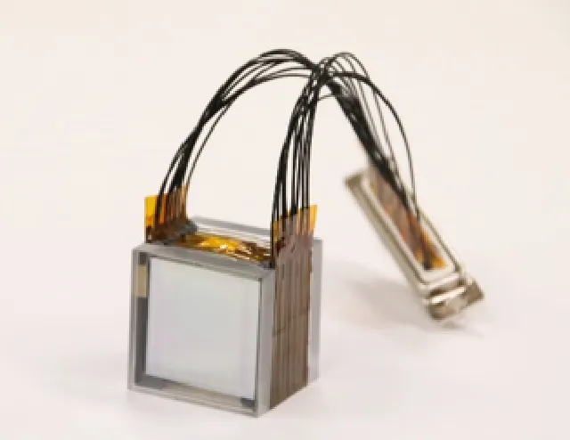
Space grade LCTF
LCTF: Liquid Crystal Tunable Filter is an optical spectroscopic device that can obtain the desired wavelength transmission by applying a specified voltage to each liquid crystal cell that comprises it. LCTF can be operated only by electronic control, it is free from mechanical troubles.
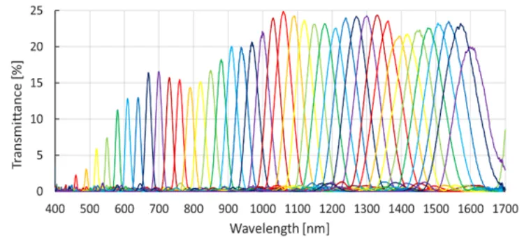
Examples of Transmission Profiles
One unit of LCTF consists of a liquid crystal cell, a polarizer and a wavelength plate, and one device of LCTF is made of those several units.
The transmittance property of each unit changes periodically with wavelength. The wavelength transmitted through each unit can be changed by applying voltage, and the transmission property of the entire LCTF, which is a series of units, is obtained as the product of the transmission properties of each unit, exhibiting a narrow bandpass property.
By controlling the voltage applied to the liquid crystal cell, the transmission center wavelength of the LCTF can be controlled arbitrarily.
By inserting LCTF into the optical path, flexible spectral observation utilizing multiple bands becomes possible, making it easy to reduce size and weight of the device.
Inappropriate transmission bandwidth during spectroscopic observation may make it impossible to cover a wide absorption band or separate multiple emission and absorption lines. Also, too narrow bandwidth may result in inadequate signal strength, which may cause insufficient signal-to-noise ratio. Currently, Genesia is collaborating with research institution to develop a new type of LCTF that can control not only the transmission center wavelength but also the transmission bandwidth by adjusting the components that constitutes the LCTF and its electrical control. This will enable the optimal transmission bandwidth and transmission wavelength for the observation target to be freely selected by software in orbit.
LCTF was developed in the United States more than 30 years ago, but it is not widely used. One of the main reasons for this is that the wavelength transmitted by LCTF depends on the angle of incidence of the light rays. When incident vertically, the longest wavelength is transmitted, and when incident obliquely, the transmitted wavelength shifts to shorter wavelength. Genesia has designed a special lens optical configuration to avoid this adverse effect and prevent wavelength shifts across the entire field of view. With this patented technology, Genesia is the only company in the world that can offer snapshot sensors using LCTF.
Since 2014, more than 10 models of the LCTF spectral imaging system have been in operation in orbit. The LCTF spectral imaging system also has a series specifically designed for installation on drones.
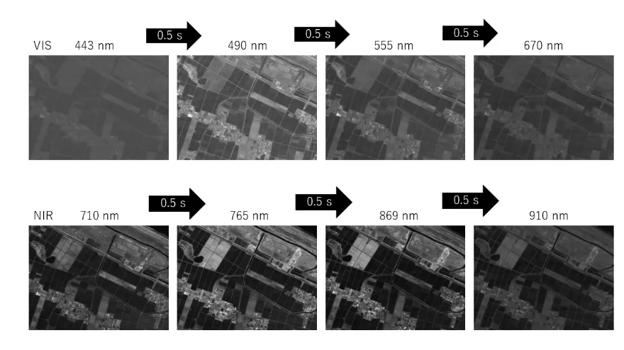
Imaging from orbit using the LCTF spectroscopic imaging system
KURIHARA et.al., “A High Spatial Resolution Multispectral Sensor on the RISESAT Microsatellite”,
Trans. JSASS Aerospace Tech. Japan Vol. 18, No. 5, pp. 186-191, 2020.
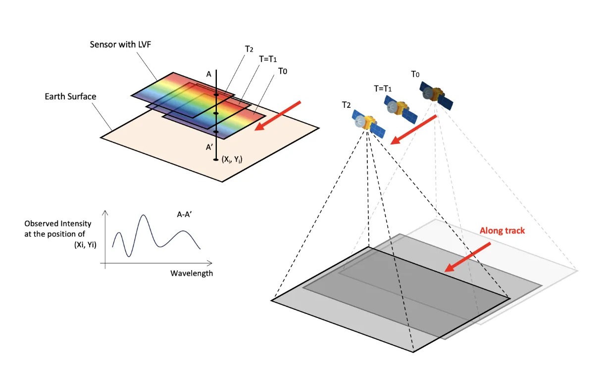
LVF: Linear Variable Filter is a type of bandpass filter. However, it does not exhibit the same wavelength transmission characteristics across the entire filter. LVF is designed so that the transmitted wavelength changes along one side of the filter. By assembling this filter and optical system and scanning images in the direction, it is possible to obtain the spectrum of the observation object. In this sense, spectral imaging using LVF can be classified as a push-broom type, similar to slit spectroscopy. However, in the case of slit spectroscopy, only the image of a one-dimensional object is wavelength-dispersed, whereas in LVF, a “series of continuous monochromatic slit images” with slight wavelength shifts are given in a two-dimensional snapshot image. Therefore, even if the attitude stability of a satellite installed with LVF is insufficient, it can be compensated for by pattern matching based on the shape characteristics of each successive instantaneous image.
LVF-type hyper sensors (multi-wavelength spectroscopic sensors) differ from other general spectroscopic devices (such as gratings, prisms, bandpass filters, and Fabry-Perot). LVF does not require collimation of the optical path for assembling spectroscopic devices, and can be simply assembled with a camera configuration consisting of a normal imaging optical system and an area sensor. In addition, the LVF spectroscopic imaging system can increase the amount of infrared light that can be used for observation by 1.5 to 2 times compared to conventional grating sensors. This is also advantageous for miniaturization of optical systems, and it is extremely promising as a candidate sensor for small satellites, not only in the visible range.
By using the LVF-type hyper sensor in push-broom mode, data can be acquired in the wavelength band of interest without relying on diffraction devices which have low light utilization efficiency.
Multi-wavelength infrared sensors that use LVF, which has high transmittance and makes it easy to get a high S/N ratio, are expected to be used in mineral resource exploration, which has a relatively broad absorption bandwidth, and marine resource development, which is characterized by low radiance.
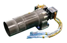
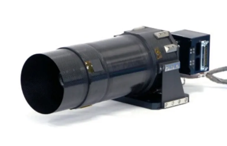
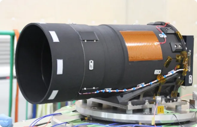
Earth observation camera installed on the “Hodoyoshi 1” satellite

Aperture 107 mm, focal length 750 mm.
Although it is a refracting telescope, it is a fully color corrected optical system
that achieves diffraction-limited performance across the entire visible wavelength range on the same image plane.
The aim was to develop and demonstrate a space telescope suitable for automatic operation with optical resolution better than 5 m, to be installed on a satellite approximately 50 cm in size.
In addition to considering launch vibration resistance and space radiation resistance in orbit, it was necessary to develop a technology (athermal and apochromatic) that could effectively eliminate chromatic aberration and maintain focus regardless of environmental changes in orbit.
By combining the effects of lens shape deformation, refractive index changes, and barrel expansion and contraction caused by environmental temperature fluctuations, it has “athermal” characteristics that enable it to maintain focus on the detector at all times. Thus, there is no need to adjust the focus of the telescope while it is in orbit. This feature has greatly contributed to the realization of automatic operation of satellite observation systems.
SHIROP installed on JAXA's super low altitude satellite “TSUBAME”
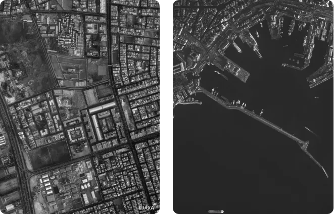
Courtesy of JAXA
By coupling optical, structural, thermal, detector electronic control, and satellite attitude control technologies, we have demonstrated that even a small telescope can observe the Earth with a ground resolution of 100 cm to 40 cm from a super-low orbit (orbit altitude of approximately 300 km).
Even with a small telescope, high spatial resolution can be expected if the satellite's orbital altitude is low. On the other hand, when the orbital altitude is low, the satellite's orbital velocity is fast, which makes image blurring more likely to occur and impairs spatial resolution. In addition, telescopes flying at super low altitudes (around 300 km) require not only the physical modifications required for conventional telescopes, but also special chemical modifications to protect them from reactive oxygen atoms in the upper atmosphere. It was necessary to develop a telescope that took these factors into consideration.
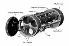
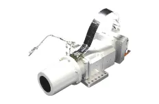
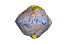
NIRS3 installed on asteroid explorer "Hayabusa2"
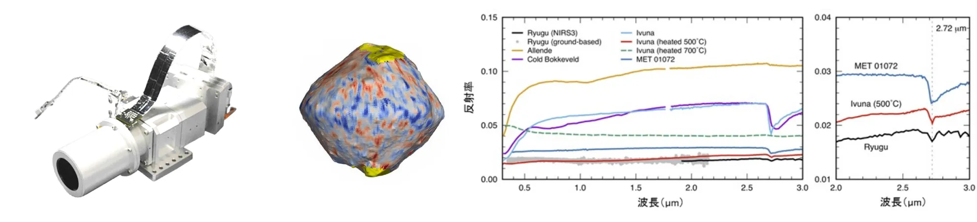
Measuring the distribution of water-bearing minerals and carbon compounds on the asteroid Ryugu
Courtesy of JAXA
A near-infrared spectroscopic camera developed to analyze the surface composition of the asteroid Ryugu. Genesis was responsible for the optical system and contributed to identifying the surface distribution of hydrated minerals. It provided the basis for determining the sample collection point on the asteroid.
The origin of humankind and its relationship to carbon compounds and hydrated minerals
brought from outside the solar system are being debated.
In the Hayabusa 2 Project, a mission to collect samples from an asteroid approaching Earth's orbit,
identifying the touchdown location was critical to the mission's success.
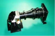
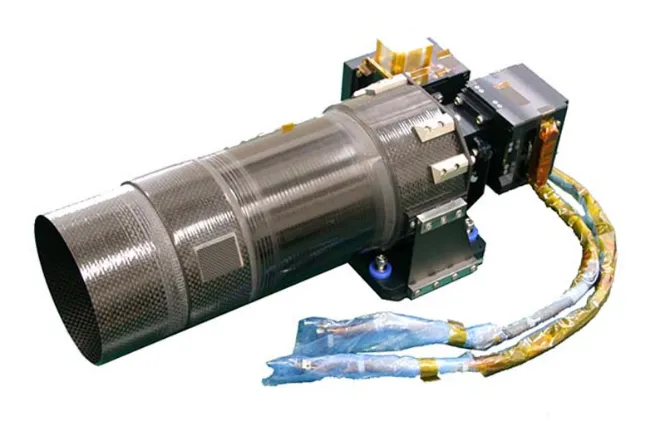
Telescope collimator for HINODE (SOLAR-B) by JAXA/National Astronomical Observatory of Japan
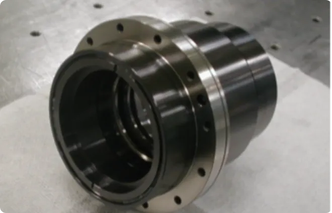
Courtesy of NAOJ
A collimator lens that combines a Japanese-made 50 cm diameter solar telescope with a US-made spectroscopic observation system. By interfacing the telescope and spectroscopic system with this collimator, it is possible to reduce the degree of coupling between the two and construct a stable space observation system.
The reason why the temperature of the upper atmosphere of the sun exceeds 1 million degrees Celsius, even though the surface temperature of the sun is 6,000 degrees Celsius, has long been a mystery in solar physics. In order to maximize the performance of the solar telescope developed to solve this mystery, it was essential to integrate a space observation system using a collimator lens.
Fully color corrected optical system that achieves six-color correction across a wide wavelength range from 450 nm to 900 nm. The thermal aberration characteristics are minimal, at 1e-6 order/K per unit focal length.
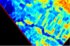
HPT installed on micro-earth observation satellite RISING-2
Courtesy of Hokkaido University
A 100 mm aperture reflecting space telescope.
The focal plane is divided into three optical paths. One of these optical paths is equipped with
a spectroscopic filter (LCTF: Liquid Crystal Tunable Filter) that can tune the transmission wavelength electronically
without mechanical drive components.
Development of a system that can efficiently and compactly achieve scientific results in agriculture, marine science, and other fields was required.
Snapshot sensors, which are compatible with 50 kg class satellites and achieve both high spatial resolution and wavelength resolution, are also advantageous in terms of relaxing the attitude stability requirements for satellites.
We have successfully achieved multi-wavelength imaging with a ground resolution of 5 m. There is no other spectral imaging sensor with more than 400 narrow-band bands.
Micro Dragon / TPI
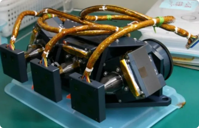
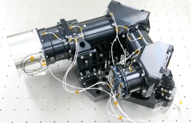
The characteristics of light as electromagnetic waves are expressed by amplitude, wavelength, and phase. This telescope aims to measure all of these simultaneously. Furthermore, it is an observation system that can be installed on small satellites.
The Earth's surface can be broadly divided into land areas and water areas, and the reflectance of sunlight and its wavelength dependence can be found in correspondence with the polarization components of reflected light. By precisely observing this, it becomes possible to accurately identify the characteristics of the observed object. This device was developed to demonstrate this.
This is a spectroscopic polarizing telescope that consists of three spectroscopic cameras with identical characteristics, arranged in a 120° symmetrical configuration to detect polarization, and configured to take images simultaneously as a set.
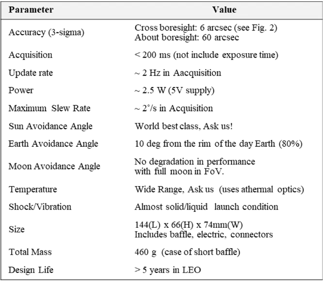
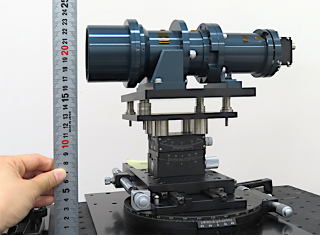
Star tracker (STT) series for small satellites
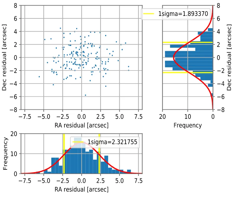
Attitude determination accuracy measured on ground
The Star Tracking Telescope (STT) is a space telescope that precisely detects the direction in which the STT itself is pointing on the celestial sphere by imaging stars. Since the STT is securely attached to the satellite structure, the direction in which the STT is pointing can be treated as basic information indicating the attitude of the satellite in the celestial coordinate space. Most space telescopes are used for missions such as Earth observation and astronomical observation, but STT is a navigation device that constitutes part of the satellite bus system.
The first unit was installed on Institute of Science Tokyo's (formerly Tokyo Institute of Technology) “HIBARA” Satellite and has been functioning normally since its launch in 2021 until now (2025).
The optical sensors used in space telescopes are constantly deteriorating due to radiation damage in orbit. This STT provided various basic information on the extent of this deterioration and ways to recover from it.
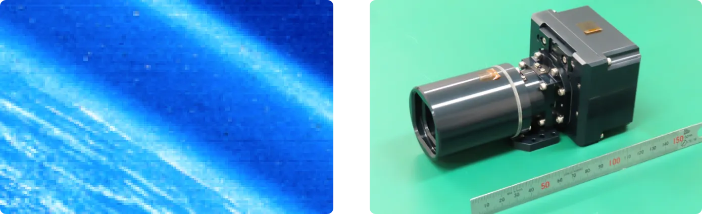
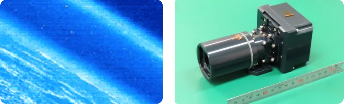
Both for Star trailing (manoeuvre) monitor & Earth surface mapping
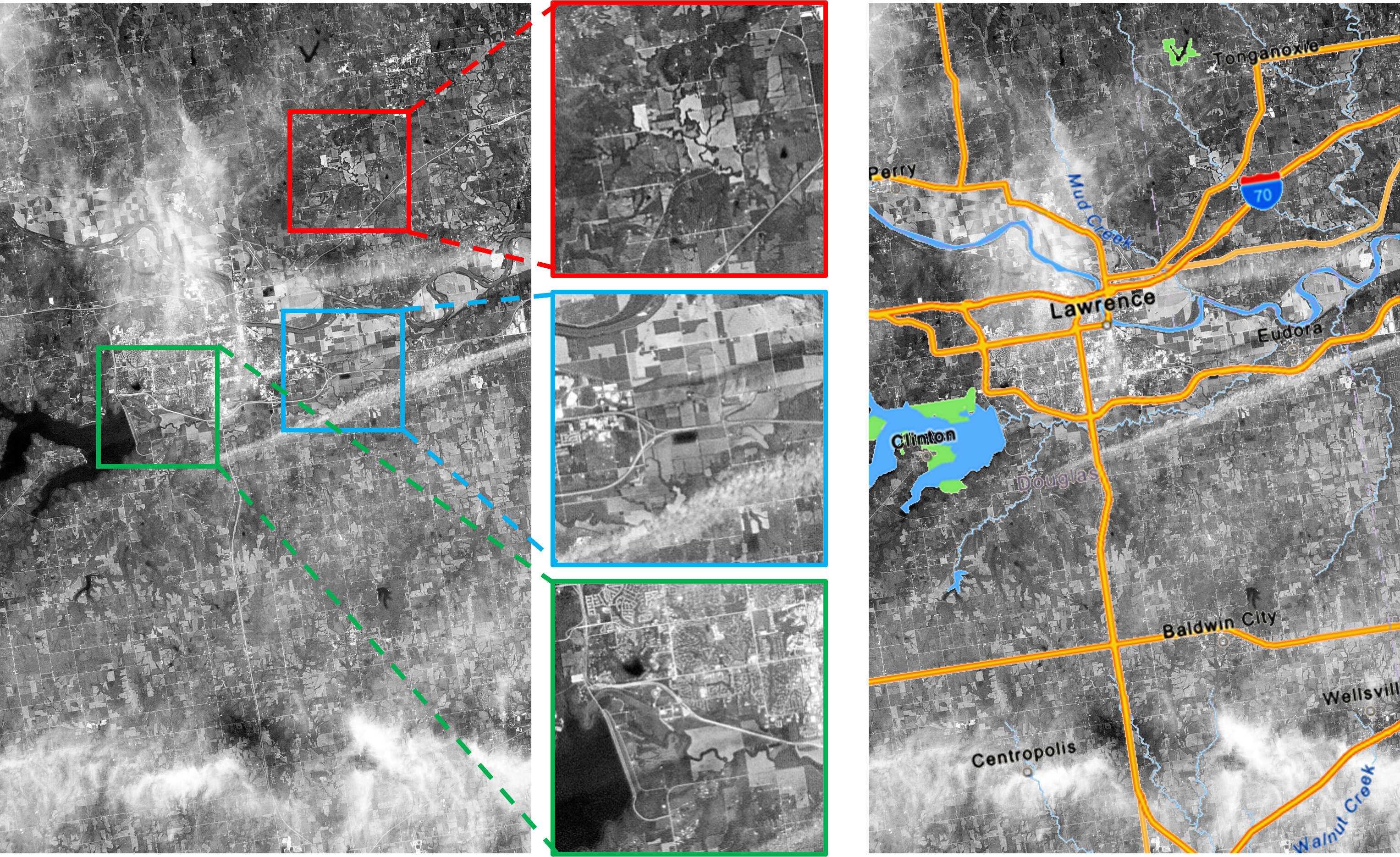
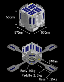
The technology demonstration satellite HIBARI, developed by Tokyo Institute of Technology (now the Institute of Science Tokyo),
captured the above image near Lawrence, Kansas, USA. One pixel in the original image corresponds to 30 meters on the ground.
Image courtesy of HIBARI team.

Click on the image to view a continuous sequence of images. (6MB)
Above Left :
HIBARI employed cutting-edge technology, using the reaction forces to control its attitude rapidly and precisely by swaying its four variable solar paddles.
Above Right :
This sequence of star-trailing images captured by the onboard Geneia camera at 1.5 second intervals across all 32 frames over a period of 48 seconds, during an attitude manoeuvre. Each image was taken with a 100 milliseconds exposure.
See detail, Kei Watanabe, Hiroyuki Kobayashi, Yuki Amaki, Toshihiro Chujo, Saburo Matunaga,“Attitude Control and on-Orbit Performance Evaluation of Spacecraft with Variable Shape Function,” Advances in Space Research, 2023. , Image courtesy of HIBARI team.